Tuesday, 20 October 2015

How does a Processor or Controller access data from Memory ? and What is Raspberry Pi ?


Accessing data from memory in a microcontroller (MCU).


Microprocessor and MCUs are different in that, microprocessors do not have inbuilt data memory (RAM) and program memory (ROM), where as MCUs have both on the chip itself.

In MCUs, operation codes, operands and results are stored in the memory space (RAM and ROM), which is organised into banks segments or pages.

Therefore an arrangement is needed for reaching a location in the data memory space, where the desired operands required by an instruction are stored and where the results after execution of the instruction, if required, are to be stored.

An addressing mode specified how to calculate the effective memory address of an operand by using the information held in registers and/or constants contained within a machine instruction.

Addressing mode depend on the design of the central processing unit (CPU), memory space and organisation of the register. These differ from MCUs of one brand to another.

There are different ways for addressing a location in the memory space, which are called immediate, register direct, absolute, address register indirect, address register relative and relative. In short, data is loaded in data memory space and has address. To get the data, the address is computed by the addressing mechanism.

Let us see how data memory is managed in microcontroller PIC18F4520. Data memory is organised in 16 banks. However, only six banks have been implemented. Each bank has 256 slots and each slot of memory can accommodate one byte or eight bits. So, the addressing mechanism has to compute the address for one slot out of 1536 slots.

Twelve bits will be needed for this; four bits from the bank selecting register (BSR) for selecting the bank. Once we are in that bank, further eight bits will be required for selecting the intended slot out of 256 slots in the made up in a different upon the addressing mode.

In direct addressing mode, all 12 bits are provided by the instruction.

In indirect addressing mode , the instruction provides the pointer and from that pointer, 12 bits are conjured to compute the selection of the bank and address of the intended location in that bank.


What is Raspberry Pi ?


Raspberry Pi, or Raspi, is a computing system that uses a Raspi board, laptop, standard keyboard, mouse, computer monitor or TV, micro USB cable, micro SD card with adaptor, HDMI cable and network cable for its operations. Programming is done in languages likes Python, Wiring Pi, C/C++ and PHP.


 It is capable of doing everything that is expected from a desktop computer, from browsing the Internet and playing high-definition video to making spreadsheets and playing games. The system has the ability to interact with the outside world and has been used in many projects, from music machines to weather station.


Raspi board has 26 dedicated GPIO pins, including a UART, an I2C bus, SPI bus with two chip selects,I2S audio, 3.3V, 5V and ground. The maximum number of GPIOs can theoretically be indefinitely expanded by making use of the I2C or SPI bus.

Interfacing of the camera module is an interesting application of Raspi. It can take high-definition videos as well as still photographs.

Thursday, 8 October 2015

7-Steps For Installing Keil uvision Software in your Computer


Now first download the Keil uvision software form its official website Download here.


Step-1:


Now, First you Install the Keil uvision software in your PC (computer) by Double click the setup file. as showing the figure.

how to install Keil in computer
Step-1


 Step-2:


Click  Next Tab to continue the process of Installing.

how to install Keil in computer

Step-2

Step-3


First, Read carefully the end user License agreement for this software then Click the agreement of software uses.

Then click Next tab to continue the setup process.


how to install Keil in computer
Step- 3

Step-4:


Here, select the computer storage path where you wish install the software. By default path is C\Keil. and Click the box of Backup old files to C\Keil\backup.003.

Then Click Next tab to continue Installation Process.

how to install Keil in computer
Step- 4

Step-5:


Fill your details like as your name,Company name,E-mail address correctly.

Then Click Next Button to start Installation Process.

how to install Keil in computer
Step- 5

Step-6:


When Installation process is start it show the status of this process as shown following figure.

how to install Keil in computer
Step- 6

Step-7:


Now  Click the three boxes as per your wish and then click to Finish button for complete Installation Process.
Now, it is ready for use.


how to install Keil in computer
Step- 7

Wednesday, 7 October 2015

How to Use Keil uvision Software for Programming


Keil uvision is best suited and more easily user friendly software for Programming of 8051 series Microcontroller. It is developed by ARM Ltd. and ARM Germany GmbH. Now, If you choose Keil software for Programming of 8051 Microcontroller that it is for you to guide how use Keil uvision software to Programming, debugging, simulating the program of 8051 Microcontroller.

Keil uvision support both C Language and Assembly Language for programming. according to me C Language is more difficulty and Lengthy to explain over the Assembly Language. Assembly Language has some Listed Instruction sets by which you can easily control and program the structure of data. you learn more about C Language and Assembly Language, Here


If you decide to program your own code for 8051 Microcontroller, then First download the Keil uvision software from their official website by using the Link below,

Keil uvision Software Download here.

7-Steps For Installing Keil uvision Software in your Computer


If you use Keil uvision in first time then you can avoid to face many trouble with the use of Keil uvision software by following steps.

14-Step to Use of Keil uvision Software for Programming :


 Step-1

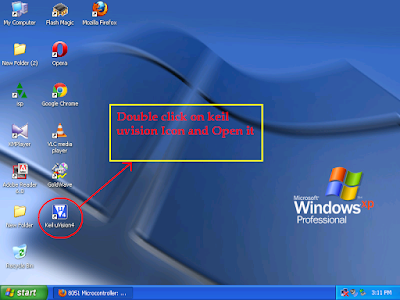
After successful installing Keil uvision software, just double click the icon on your desktop as shown in figure to open it.
use of keil uviion software
Step-1


Step-2

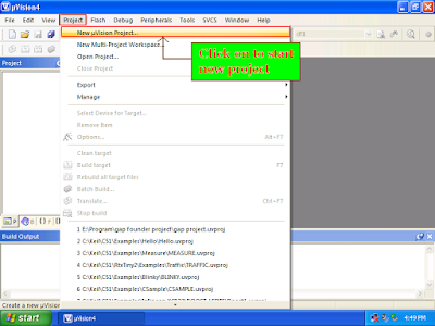
Now, create the new Project by clicking the Projects tab in Menu bar.

use of keil uviion software
Step-2

Step-3

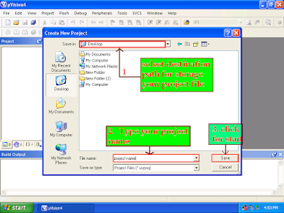
Select the path, where you wish to store the Project file and give your Project Name.

use of keil uviion software
Step-3

Step-4

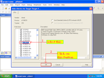
After complete the Step-3, a screen will appear as shown below. In this select the Controller which is used for this Project.

use of keil uviion software
Step-4

Step-5 

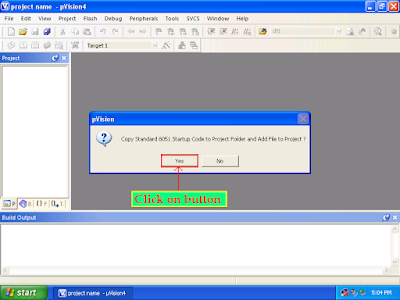
If you write your Program in C language then click yes  in following dialog box. it is a start up file which initialize the controller. If you Write your Program in Assembly Language then click No tab, because it is not required for assembly language.

use of keil uviion software
Step-5


Step-6

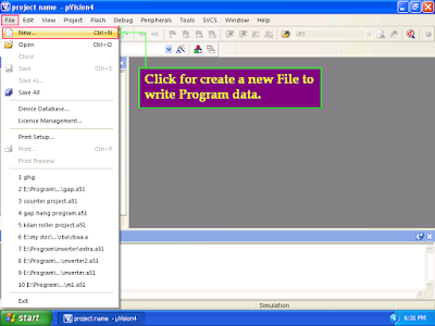
Now, you need to create a new file to write your program.

use of keil uviion software
Step-6

Step-7

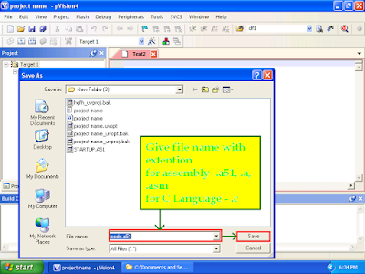
Give your program file name with following extension.

For Assembly Language -    .a51  ,   .a  ,   .asm
        example : Program.a51  /  Program.a  /  Program.asm

And for C Language -   .c    
         example : Program.c

use of keil uviion software
Step-7

Step-8

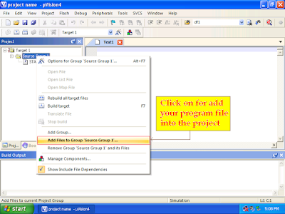
Now, you require to add your Program file to your Project.
use of keil uviion software
Step-8

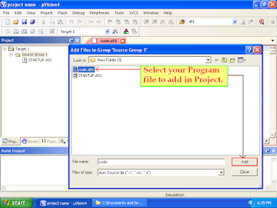
Step-9

Select your Program file and click add Button.

use of keil uviion software
Step-9


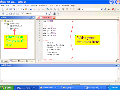
Step-10

The added Program file is Shown in your Projects List as shown bellowing figure. Now, you can start to write your program in right hand side window.

use of keil uviion software
Step-10


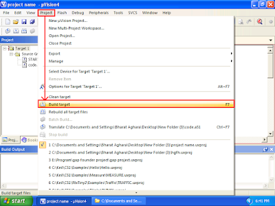
Step-11

After writing  Program, you need to create build target for detecting the errors related to your program like as syntax errors, warnings, etc.

use of keil uviion software
Step-11


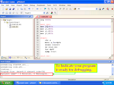
Step-12

The Errors and Warnings related to your Program is shown in bottom window. For next step, you solve it first if any errors and warnings generate and rebuild target until it should be Zero.

use of keil uviion software
Step-12

Step-13

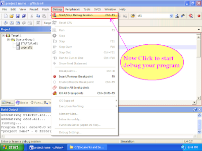
After Complete the Step-12 , you are able to debugging your program for simulate and analysis

use of keil uviion software
Step-13

Step-14

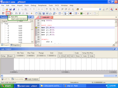
Now, you can run the Program for simulate and you analyze your program. you also watch the logic Analyzer for showing the status of pin logic as per your program and much more as you done.

use of keil uviion software
Step-14


Thursday, 1 October 2015

GSM Modem Interface with 8051 Microcontroller

How to Interface GSM (Sim900 / Sim300) Module with 8051 Microcontroller (89s52 Microcontroller) ?

GSM Sim300 ModemGSM Sim900 Modem


Sim900 / Sim300 is a one type of GSM Module Which support the AT command and used for Mobile communication. It is mostly used to interface with 8051 Microcontroller in Various Projects Like as, SMS sending, Call handling, GPRS based, Home Security System,etc.

Learn More about AT Commands,Click here.


What is GSM Modem?

The GSM Modem (Sim900/Sim300) has a Sim Slot similar to a mobile to communicate by mobile networks. It operate by AT Commands and it Response only for AT Commands. 

What is Difference between Sim900 and Sim300 Module ?

For basic Guideline, Concepts, Working and operation of AT commands and GSM Module refer- GSM/GPRS Module details. 

Here the Circuit Diagram for Interfacing Sim900 / Sim300 with 8051 Microcontroller (89s52-Microcontroller) is given below,


Here, We use Atmel 89s52 Microcontroller (Which is from 8051 Microcontroller Family) to Interface with GSM modem. The interface between GSM module and Microcontroller is take place by Rs232 Communication.

The GSM module (Sim900/Sim300) has inbuilt MAX232 ic for Rs232 communication,which is showing in following figure,


But, the extra MAX232 Circuit is need to Microcontroller side to complete communication occurs between GSM module and 8051 Microcontroller.

RS232 Communication Circuit by using MAX232 ic for Microcontroller

Max232 ic Circuit diagram for RS232 communication


Why MAX232 ic is Used for Microcontroller?

MAX232 ic is used for Converting the Logic Level Signal. The GSM module Gives signal as Rs232 Logic level. When the Microcontroller works on TTL logic Signal. so, A Converter device is require for this, to convert the Rs232 Logic level signal into TTL Logic level signal. MAX232 ic is used for this Purpose.

Here, Listed Some Program example for various Projects based on GSM modem, to Learn more about working of GSM Modem and How it actually work?

1.)   Home Security System by Using Sim900 Modem.
2.)   A message send by GSM Sim900/Sim300 modem.
3.)   A call handle by Sim900/Sim300 Modem.
4.)   A device Control through a message by using Sim900 modem.
5.)   A device Control through a Call by using Sim900 modem.
6.)   Sim300/ Sim900 Power supply Circuit diagram.


Tuesday, 29 September 2015

ULN 2003 Relay Driver Circuit For 8051 Microcontroller


We can not Directly drive the Relay through Microcontroller. Because the Microcontroller Gives only Regulating Pulse ( Drive Pulse to ON/OFF ) (0 or 1). Which is not capable to drive the Relay coil directly. The Relay coil (12 volt) can energies at +12volt supply, at this time the coil take dc current approx 20-25 ma.
Thus the total Power required by Relay coil for energies is,

Power =  Volt * Current
           =   12 * 0.020
           =   0.240 mw

Microcontroller does not Provide sufficient Current for this Operation. It provide only a few micro-ampere or Milli-ampere current for such any application control like as LED, 16*2 LCD display, Transistor drive,etc.

Thus the Relay Operate with 240 milli-watt power. The Microcontroller give only a few micro-watt or milli-watt power which is only Describe as Signal.
ULN2003
Thus we require a second part which can deliver the power as per requirement of Relay coil, and operate by Microcontroller Signal pulse.

ULN2003 ic is introduce for this purpose. it is CMOS ic, which is specially design for relay drive with including free welling Diode and Buffer Circuit. The ic UlN2003 is capable for operate seven no of Relay with seperately operation.
It has also seven separate Input for drive the seven Relay separately.

Circuit Diagram: 

 
circuit diagram of UlN2003 Interfacing with 8051 Microcontroller


Friday, 25 September 2015

How to Use Port Pin of 8051 Microcontroller as Input or Output

The Port0, Port1, Port2, Port3 of 8051 Microcontroller is individually use as Input or Output as per Requirement of User Program. We can use this Port Pins either Input or Output.

Port Pins Use as Input Pin of 8051 Microcontroller: 

First all of this, We can decide which Pin is use for Input Pin. Suppose, the Pin P1.0 is use for Input Pin. So, In the Program We set First this Pin as High Logic by using following Instruction set....

org 0000h
 port_ini:
      setb p1.0               //   P1.0 is set high for Input   //  
.
.
.
Program
.
.
.
end


Note:-  Which Pin or Port is use for Input of 8051 Microcontroller is First set for 1 of it by Software (Program). So the Microcontroller is Understand that this Port or Pin used for Input and take Data by this Pin or Port. As same Which Pin or Port is use for Output of 8051 Microcontroller is First clear for 0 of it by Software or Program, So that the Microcontroller is Understand that this Pin or Port used for Output.


Circuit Diagram:

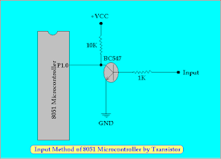
Input Method of 8051 Microcontroller

Here Pull up Register is Connected to the Pin P1.0 because it make a Strong Input Signal as the Form of Voltage and Current. here the Input is given to the NPN Transistor to drive the P1.0 Pin as High or Low.

When the Input Signal is High (1) , +VCC is Connected to the Base of Transistor. Thus the Transistor Conduct and the Pin P1.0 is becomes Low (0). We can also use PNP Transistor in the place of NPN Transistor per our Requirement of Input Logic. We can also use Optocoupler at the place of Transistor. It is Best Suitable where Isolation is Require between the Control Circuit and Driver Circuit.


Port Pin use as output Pin of 8051 Microcontroller:

All Processor and Controller is work only on Logic Levels. It can not Provide Sufficient Signal as the form of Voltage and Current. So, it can not drive Directly heavy Load. The 8051 Microcontroller Belong to them. So, the Driver Circuit or Topology is Require for Operation. We can use Transistor, Optocoupler, amplifier Circuit, IGBT, MOSFET as a Driver as per Load Requirement. 

Here Simple Driver Circuit by Only One Transistor is connected to the Microcontroller which is Capable to Drive Load like as Relay, Led, Buzzer.

Circuit Diagram:

Output Method of 8051 Microcontroller


 Now, First all of this We decide that which Pin is Used for Output pin of Microcontroller. Suppose P1.0 Pin of Microcontroller is use for Output Pin, Thus, clear this Pin by Software or Program by giving CLR P1.0 Instruction to the Microcontroller. So the Microcontroller set this Pin as Output Pin.

org 0000h
Port_ini:
        clr P1.0         //   Initialize P1.0 as Output Pin  //
.
.
.
Program
.
.
.
end  


Here, Pull up Register is Require to make a Logic Signal Strong as form of Voltage and Current by that the Sufficient Current and Voltage is Provide to Drive the Transistor. When P1.0 is set to High (1), the Transistor give the Base Voltage and it is conduct. Thus the Load connected to the transistor is active by passing Collector Current through the Load. When P1.0 is clear(0), the Transistor remains off and thus load also remains Off  because the absence of Collector Current. We can also use the PNP Transistor for opposite the above Work Logic as per User requirement.

Thursday, 24 September 2015

Interfacing 16*2 LCD With 8051 Microcontroller

What Is  16*2 LCD ?


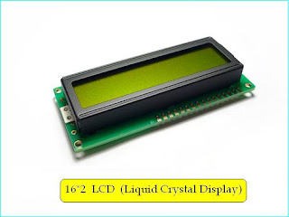
The LCD ( liquid crystal display) is device to good communicate between user and machine. It display the Software status, Errors, Indicators, Data as per user program by which a good Control method and a good communication occurs between user and electronics system and make a more user Friendly and attractive.
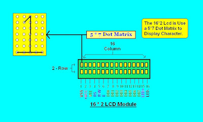
16*2 LCD Display
16*2 LCD Display

Features:

Lcd displays are widely used because of its low current consumption as compared to seven segment displays. And another, it is more attractive to the seven segment display (SSD).

16*2 LCD is mostly used to interfacing of 8051 Microcontroller.


 How 16*2 LCD Interface With 8051 Microcontroller ?


Pin Description and  Details of 16*2 LCD
Pin Description and  Details of 16*2 LCD

 Applications:

  1. Digital Voltmeter / Ammeter.
  2. Digital Speedometer / odometer.
  3. Home Automation System.
  4. Display for Music Player.
  5. Status Indicator Display.
  6. Digital Clock. 

Command to Operate 16*2 LCD Display Module:

      
            Hex Code                            Work Function
               38h         -        Initialize 2 line display of 5*7 Matrix.
               01h         -        Clear Display
               02h         -        Cursor Return to Home        
               04h         -        Decrement Cursor ( in Left Side )
               05h         -        Shift Display Right
               06h         -        Increment Cursor ( in Right Side )
               07h         -        Shift Display Left Side
               08h         -        Display Off & Cursor Off
               0ah         -        Display Off & Cursor On
               0ch         -        Display On & Cursor Off
               0eh         -        Display On & Cursor On
               0fh          -        Display On & Cursor On and Blinking
               10h         -        Move Cursor One Position Left Side
               14h         -        Move to Cursor One Position Right Side
               18h         -        Shift Entire Display Left Side
               1ch         -        Shift Entire Display Right Side
               80h         -        Move Cursor to Beginning of 1st Line
               c0h                  Move Cursor to Beginning of 2nd Line


How 16*2 LCD Display Work? How We can Display Message on 16*2 LCD? How to Initialization of 16*2 LCD? LCD Initialization........

  1. Give the Supply and Wait for a Second to Stabilize the Display.
  2. Give the Instruction 38h for Initialize 2 Line display of 5*7 Matrix LCD.
  3. Wait for a few millisecond (approx 5ms) to Complete Operation and LCD take Action as per given Command.
  4. Give 0fh Command to Display ON & Cursor ON and Blinking.
  5. Wait for some time (approx 5 ms).
  6. Give command 01h to clear the Display of LCD.
  7. Wait for some time (approx 5ms).
  8. Give command 06h for making Increment Cursor mode of LCD. By this, cursor should increase after every Character is Written to display automatically.
  9. Wait for some time (approx 5 ms).   
  10. Give the command 80h for Cursor take position at 1st Line 1st Character.
This above 10 step is Require and Basic Common Instruction for 16*2 LCD Initialization. Thus it write to start up of every Program Related to the LCD Projects. Then the User can Program to display the Data or Information on LCD as per requirement of User. This is Explain with a Short Program example of to Display the "Welcome to Here" on the LCD Display.

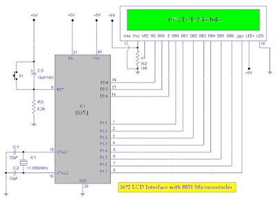
Circuit Diagram: 

 
Circuit diagram of LCD interfacing with 8051 Microcontroller

Assembly Language  Program to Display "Welcome to Here" in 16*2 LCD Display:

org 0000h

port_ini:
mov p1,#00h
setb p3.4
setb p3.5
setb p3.6
acall delay_1s

Lcd_ini:
mov a,#38h
acall command
mov a,#06h
acall command
mov a,#0ch
acall command
mov a,#01h
acall command
mov a,#80h
acall command
acall delay_1s
Display:
mov a,#'W'
acall write
mov a,#'e'
acall write
mov a,#'l'
acall write
mov a,#'c'
acall write
mov a,#'o'
acall write
mov a,#'m'
acall write
mov a,#'e'
acall write

mov a,#14h
acall command

mov a,#'t'
acall write
mov a,#'o'
acall write

mov a,#14h
acall command

mov a,#'H'
acall write
mov a,#'e'
acall write
mov a,#'r'
acall write
mov a,#'e'
acall write

here:
sjmp here

;;;;;;;;;;;;;;;;;;;;;;;;;;;;;;;;;;;;;;;;;;;;;;;;;;;;;;;;;;;;;;;;;;;;;;;;;;;;;;;;;;;

command:
mov p1,a
clr p3.4
clr p3.5
setb p3.6
acall delay
clr p3.6
acall delay
acall delay
ret

write:
lcall ready
mov p1,a
setb p3.4
clr p3.5
setb p3.6
acall delay
clr p3.6
acall delay
acall delay
ret

ready:
setb p1.7
clr p3.4
setb p3.5
wait:
clr p3.6
acall delay
setb p3.6
jb p1.7,wait
ret

delay:
mov r0,#1ch
rep:
djnz r0,rep
ret
delay_1s:
mov r3,#08h
df1s:
mov r2,#0ffh
d1s:
mov r1,#0ffh
de1s:
djnz r1,de1s
djnz r2,d1s
djnz r3,df1s
ret

end

Sunday, 13 September 2015

Programmer Circuit of P89V51RD2

Programmer Circuit of Phillips P89V51RD2 Microcontroller and other family ic of 8051 series Microcontroller by using ISP (In-Application Programmable) Programming Method.


Here in this circuit the TX and Rx data transmission pins p3.0 and p3.1 of  P89V51RD2 Microcontroller is used 
for programming by ISP method via serial RS232 communication.

Here noted that EA pin of P89V51RD2 Microcontroller must 

be connected to +VCC of power supply.

The circuit diagram:

Programmer Circuit of  P89V51RD2 Microcontroller
Programmer Circuit of  P89V51RD2 Microcontroller

Here max232 ic used for converts the voltage levels from RS232 to TTL  voltage levels and vice verse, because we know that the RS232 is not computable with the TTL logic levels. Hence the converter need for it.


What is RS232 Standard? 


In the early 1960s a standards committee today know as the electronic industries association (EIA) , developed a common interface standard for data communications equipment to ensure reliable communications and second to enable to interconnection of equipment produced by different manufacturers and fostering the benefits of mass production and competition. From this idea, the RS232 standard was born. It specified signal voltages, signal timing, signal function, a protocol for information exchange and mechanical connectors.


Step for Programming:


Here are the steps to program P89V51RD2 by ISP method using RS232


Click the below link for download flash magic software:


For windows xp / vista / 7 / 8

for mac OS x10.6+
http://www.flashmagictool.com/download.html&d=Flashmagic.app.dmg

Flash Magic For Programming P89V51RD2 Microcontroller

Download and Open flash magic software
Connect programmer circuit to your computer via DB9 socket and power up your circuit.

step-1:


choose following data
device : P89v51rd2
com port  :  com1
Baud Rate : 9600
Interface : None(ISP)
Oscillator(MHZ) : 12.000
Step-1 For Programming Microcontroller


Step-2 :


Don not check the Erase all Flash code . it will erase all data 
include the Boot loader program 
 data in micro controller so, do not check it.
If you reprogramming the Micro controller you will check the Erase blocks used by hex file.
Step-2 For Programming Microcontroller


Step-3:


 Select the hex file, which you want to programing in to the

 Microcontroller.

Step-3 For Programming Microcontroller


Step-4 :

 
Check the verify after programing and other may use as per 
 
 user want. 
Step-4 For Programming Microcontroller


Step-5:


Click the start button for starting the programing of 

Microcontroller. 
Step-5 For Programming Microcontroller


Related Links:

Product Page: http://www.semiconductors.Philips.com/
 

Data Sheet: P89V51RB2_RC2_RD2-03.pdf
 

Boot Loader: p89v_lv51rd2_bl_upd_v5.zip
 

Flash Magic ISP Software: http://www.esacademy.com/

Search Keywords :


1. Programmer Circuit of P89v51rd2           Microcontroller

2. Programming Method of Microcontroller

3. Phillips P89v51rd2 Microcontroller

4. Development of Microcontroller

5. Basic of Microcontroller