The Port0, Port1, Port2, Port3 of 8051 Microcontroller is individually use as Input or Output as per Requirement of User Program. We can use this Port Pins either Input or Output.
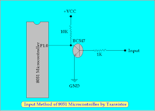
Here Pull up Register is Connected to the Pin P1.0 because it make a Strong Input Signal as the Form of Voltage and Current. here the Input is given to the NPN Transistor to drive the P1.0 Pin as High or Low.
When the Input Signal is High (1) , +VCC is Connected to the Base of Transistor. Thus the Transistor Conduct and the Pin P1.0 is becomes Low (0). We can also use PNP Transistor in the place of NPN Transistor per our Requirement of Input Logic. We can also use Optocoupler at the place of Transistor. It is Best Suitable where Isolation is Require between the Control Circuit and Driver Circuit.
Port Pins Use as Input Pin of 8051 Microcontroller:
First all of this, We can decide which Pin is use for Input Pin. Suppose, the Pin P1.0 is use for Input Pin. So, In the Program We set First this Pin as High Logic by using following Instruction set....
org 0000h
port_ini:
setb p1.0 // P1.0 is set high for Input //
.
.
.
Program
.
.
.
end
Note:- Which Pin or Port is use for Input of 8051 Microcontroller is First set for 1 of it by Software (Program). So the Microcontroller is Understand that this Port or Pin used for Input and take Data by this Pin or Port. As same Which Pin or Port is use for Output of 8051 Microcontroller is First clear for 0 of it by Software or Program, So that the Microcontroller is Understand that this Pin or Port used for Output.
Circuit Diagram:
 |
| Input Method of 8051 Microcontroller |
Here Pull up Register is Connected to the Pin P1.0 because it make a Strong Input Signal as the Form of Voltage and Current. here the Input is given to the NPN Transistor to drive the P1.0 Pin as High or Low.
When the Input Signal is High (1) , +VCC is Connected to the Base of Transistor. Thus the Transistor Conduct and the Pin P1.0 is becomes Low (0). We can also use PNP Transistor in the place of NPN Transistor per our Requirement of Input Logic. We can also use Optocoupler at the place of Transistor. It is Best Suitable where Isolation is Require between the Control Circuit and Driver Circuit.
Port Pin use as output Pin of 8051 Microcontroller:
All Processor and Controller is work only on Logic Levels. It can not Provide Sufficient Signal as the form of Voltage and Current. So, it can not drive Directly heavy Load. The 8051 Microcontroller Belong to them. So, the Driver Circuit or Topology is Require for Operation. We can use Transistor, Optocoupler, amplifier Circuit, IGBT, MOSFET as a Driver as per Load Requirement.
Here Simple Driver Circuit by Only One Transistor is connected to the Microcontroller which is Capable to Drive Load like as Relay, Led, Buzzer.
Circuit Diagram:
 |
| Output Method of 8051 Microcontroller |
Now, First all of this We decide that which Pin is Used for Output pin of Microcontroller. Suppose P1.0 Pin of Microcontroller is use for Output Pin, Thus, clear this Pin by Software or Program by giving CLR P1.0 Instruction to the Microcontroller. So the Microcontroller set this Pin as Output Pin.
org 0000h
Port_ini:
clr P1.0 // Initialize P1.0 as Output Pin //
.
.
.
Program
.
.
.
end
Here, Pull up Register is Require to make a Logic Signal Strong as form of Voltage and Current by that the Sufficient Current and Voltage is Provide to Drive the Transistor. When P1.0 is set to High (1), the Transistor give the Base Voltage and it is conduct. Thus the Load connected to the transistor is active by passing Collector Current through the Load. When P1.0 is clear(0), the Transistor remains off and thus load also remains Off because the absence of Collector Current. We can also use the PNP Transistor for opposite the above Work Logic as per User requirement.
No comments:
Post a Comment